| BNC CONNECTOR |
 Description
|
BNC connectors are one of the world's most popular
RF connectors. BNC connectors are applicable from DC up to 4 GHz with
50 ohms and from DC up to 1GHz with 75 ohms characteristic impedance. |
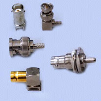
BNC Type RF Coaxial Connectors for A/V Equipment
|
|
Key Specifications/Special Features:
- Applicable from DC up to 4GHz with 50 ohms and from DC up to 1GHz
with 75 ohms characteristic impendance
- Connector body:
Material: brass
Finish: nickel or gold plating
- Center contact:
Male: brass
Female: beryllium copper, phosphor bronze
Finish: gold plating/gold plating
- Insulation
Material: PP or teflon
Finish: none
- Gasket
Material: silicone rubber
Finish: none
- Crimp ferrule
Material: annealed copper
Finish: same as body
- Electrical
Impedance: 50 ohms
Frequency range: 4GHz
VSWR: 1.3 max
Working voltage: 500 volts rms
Contact resistance: center contact 4.0 milliohms max, outer contact
1.5 milliohms max
Insulation resistance: 5000 megohms min
Dielectric withstanding voltage: 1500 volts rms
- Mechanical and environmental
Mating: bayonet lock coupling
Durability: 500 matings
Cable retention: 40 lbs min
Coupling nut retention: 50 lbs min
Temperature range:
:: PP: -45 to +85 degrees Celsius
:: Teflon: -65 to +165 degrees Celsius
Vibration: MIL-STD-202 method 204 test condition D
Thermal shock: MIL-STD-202 method 213 test condition I
Corrosion: MIL-STD-202 method 101 test condition B
|
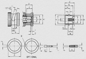
| PLUG |
| Letter |
MINIMUM |
MAXIMUM |
| A |
 9.78 m/m
 |
9.91 m/m |
| B |
7.92 m/m |
8.10 m/m |
| C |
4.88 m/m |
4.93 m/m |
| D |
5.31 m/m |
5.38 m/m |
| E |
5.38 m/m |
5.54 m/m |
| F |
0.15 m/m |
0.30 m/m |
| G |
0.08 m/m |
1.02 m/m |
| H |
1.40 m/m |
1.65 m/m |
| I |
1.35 m/m |
1.37 m/m |
| J |
2.31 m/m |
2.46 m/m |
| K |
2.16 m/m |
2.18 m/m |
| L |
2.31 m/m |
2.46 m/m |
| M |
0.46 m/m |
0.56 m/m |
| N |
4.57 m/m |
4.67 m/m |
| O |
3.15 m/m |
|
| P |
11.76 m/m |
12.01 m/m |
| Q |
|
|
|
| JACK |
| Letter |
MINIMUM |
MAXIMUM |
| A |
10.97 m/m |
11.07 m/m |
| B |
9.60 m/m |
9.68 m/m |
| C |
8.31 m/m |
8.46 m/m |
| D |
8.10 m/m |
8.15 m/m |
| E |
4.67 m/m |
4.72 m/m |
| F |
6.95 m/m |
7.01 m/m |
| G |
10.52 m/m |
|
| H |
5.18 m/m |
5.28 m/m |
I |
1.91 m/m |
2.00 m/m |
J |
0.00 m/m |
0.15 m/m |
K |
0.38 m/m |
0.76 m/m |
L |
5.21 m/m |
5.28 m/m |
M |
5.08 m/m |
5.28 m/m |
N |
5.21 m/m |
|
O |
1.52 m/m |
1.58 m/m |
P |
2.08 m/m |
2.13 m/m |
Q |
1.14 m/m |
1.24 m/m |
|
| Material |
| |
Material |
Finish |
| Connector body |
Brass |
Nickel or gold plating |
| Center contact |
Male-Brass |
Gold plating |
| Female-(1)Beryllium copper
(2)Phosphor bronge |
Gold plating |
| Insulation |
PP or Teflon |
None |
| Gasket |
Silicone Rubber |
None |
| Crimp ferrule |
Annealed copper |
Same as body |
|
| Electrical |
| Impedance |
50 ohms |
| Frequency
Range |
4GHz |
| VSWR |
1.3 max |
| Working
Voltage |
500 volts rms |
| Contact
Resistance |
center contact 4.0Milliohms max
outer contact 1.5 Milliohms max |
| Insulation Resistance |
5000 Megohms min |
| Dielectric withstanding Voltage |
1500 Volts rms |
|
| Mechanical & Environmental |
| Mating |
Snap-on coupling |
| Durability |
500 matings |
| Cable Retention |
10 lbs min |
| Coupling
Nut Retention |
40 lbs min |
| Temperature Range |
'-25'C TO +125'C |
| Vibration |
MIL-STD-202 Method 204 Test Cond D |
| Thermal Shock |
MIL-STD-202 Method 213 Test Cond I |
| Corrosion |
MIL-STD-202 Method 101 Test Cond B |
|
Copyright© 2004 cableslink.com, all rights reserved.